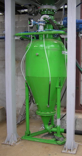
Description
 Chamber feeder consists of a cylindrical pressure vessel with a tapered bottom part fitted 18 pieces of special fluidizačních nozzles. At the top and bottom of the Bowl are installed capacitive sensors levels indicating the level of the material during the working cycle. In the upper part of the container are two holes fitted with pneumatic ovládanýmí closures. One is used to the pressure and the other for the implementation of the container material. Also the exit hole located in the bottom of the container is equipped with a controlled closing device. The whole water vessel, including the fluidizačních nozzle is connected to the distribution of a modified air pressure.
The use of the
Pneumaticka transport of dry powder materials with a maximum size of up to 4 mm. The standard length of a transport pipe 300 m elevation 30 m. Chamber feeder is primarily intended for connection with transport by pipeline equipped along the route (at least in the introductory section) fluidizačními jets.
Function
Chamber feeder works in cycles. In the stage of filling phase are both locks, decompression and filling, open the dust and material flows into the container until the level of the material in the container has reached the top of the sensor guard. Then the two previously mentioned caps closed. The main compressed air cap is opened and the pressurization phase occurs on the vessel and fluidizace material. After a few seconds the discharge valve is opened and the material is transported by means of transport by pipeline. The rate of transport is easily adjustable by setting the valves. The material is transported so long until the level of material in the Chamber reaches the sensor guard bottom feeder level material. Then the two caps, compression and discharge, concluded. The next cycle begins with the opening of the decompression and the filling cap. The operation takes place in a fully automated mode. The control unit that controls the setting of the valve is fully compatible with conventional technological control systems.
The parameters of the
| The volume of the Chamber feeder | 0.4 to 4 m3 |
| Body weight feeder | approx. 300-1400kg |
| The thickness of the walls of the Chamber | 10/12/14 mm |
| Max. the weight of the one carried by the benefits | 5000 kg |
| Max. the transmission cant | 40 m * |
| Max. the length of the transport pipeline transport | 300 m * |
| Time to flush the Chamber feeder | 2 ÷ 6 minutes * |
| The period of performance of the Chamber feeder | 10 ÷ 60 s |
| The time range of complete cycle | 3 ÷ 7 min |
| The operating range of the working air pressure | 0.4 ÷ 0.5 MPa |
| Average air consumption for transport material | 300 ÷ 600 m3/hour * |
| Peak air consumption at max. pressure load | 1200 m3/h |
| Max. bulk density of the transported material | 1600 kg/m3 |
| Max. grain size material | 4 mm |
| Max. leave the moisture of the material | 0.2% |
The Parameters depend on the quality and the characteristics of the transported material.
